Technical
Current Engineering Baseline — Supersedes earlier v26 pre-FAT draft specifications
HYDRO PULS DIRECT-DRIVE (HPDD) — TECHNICAL SPECIFICATIONS
1. Two-Circuit Architecture: Zero-Carbon Fuel Reaction + Hermetically Sealed Internal Loops
To eliminate exhaust stacks, cooling towers, and fluid losses, HPDD separates the zero-carbon fuel reaction from three hermetically sealed internal working circuits:
• Zero-Carbon Ammonia Reaction (NH3 + Air → N2 + H2O):
Liquid green ammonia (NH3) reacts stoichiometrically with oxygen from ambient air (4 NH3 + 3 O2 → 2 N2 + 6 H2O + Heat), accelerated by recuperative in-situ catalytic hydrogen enrichment powered entirely by internal waste heat (< 374 °C, zero external heater penalty). Peak combustion temperatures are actively moderated so NOx formation is suppressed, producing only pure nitrogen (N2) and superheated water vapor (H2O) with zero carbon (0 CO2).
• No Exhaust Plume — Internal Condensation & Separation:
Instead of venting hot gases up an exhaust stack, reaction steam is condensed internally into pure, mineral-free distilled water (~0.42 L/kWh; 126 L/hr per 300 kW module / ~4,160 L/hr per 10 MW), while clean, dry nitrogen (N2) is separated for internal pressure-loop replenishment and on-site industrial/fire-suppression use.
• Three Hermetically Sealed Internal Loops (Δm = 0.000 kg Working-Fluid Loss):
1. Closed-Loop Hydrostatic Water Bearing & Injection Circuit: Demineralized process water forms a frictionless hydrostatic film between piston and cylinder liner and recirculates in a closed loop with zero net water consumption.
2. +600 Bar Hydrostatic Power-Transfer Circuit: Linear piston force transfers directly into a sealed +600 bar hydraulic column without crankshafts, connecting rods, or gearboxes.
3. Unpressurized 230 °C Siloxane Thermal Stabilization Loop: Maintains the engine block at an isothermal 230 °C baseline and routes high-grade process heat directly to downstream desalination (ACR/VCD), chemical upgrading, or facility heating, eliminating external cooling towers.
2. Core Engineering Parameters (Single 300 kW Module)
• Electrical Output & Scalability: 300 kW nominal per module (scalable from 160 kW to 600 kW at up to 200 Hz; containerized multi-module arrays to 10 MW+)
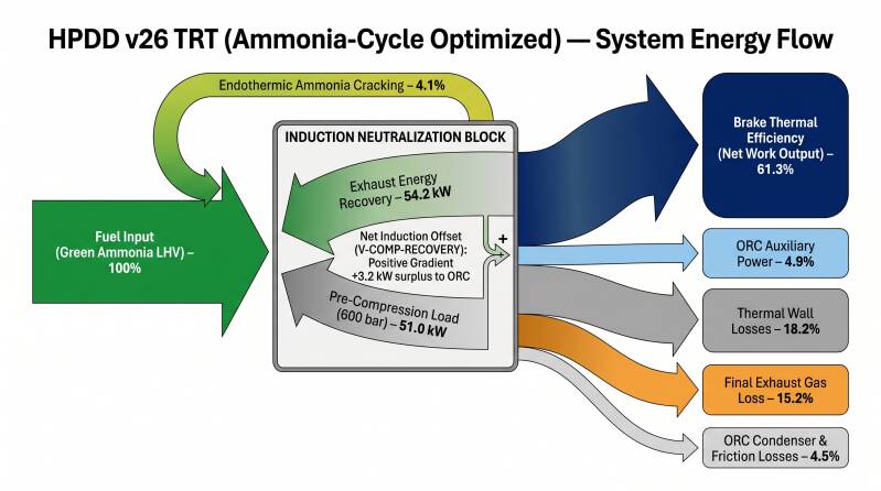
• Net Electrical / Thermal Efficiency: ~63% net electrical efficiency (> 85% combined heat & power utilization)
• Peak Operating Pressure: +600 bar continuous hydrostatic drive
• Operating Temperature Standard: 230 °C isothermal baseline (unpressurized closed-loop siloxane circuit)
• Mechanical Architecture: 4 pairs of horizontally opposed free pistons (8 pistons total) , self-canceling inertia, virtually zero structural vibration, zero engine lube oil
• Metallurgy & Precision Clearance: Matched Inconel cylinder bore and pistons (equal 109 µm thermal expansion at 230 °C) maintaining a constant 25 µm radial clearance (35 µm at combustion chamber end)
• Emissions & Byproducts: 0 CO2, 0 NOx, 0 soot, no exhaust stack; co-produces ~126 L/hr (~3.0 m³/day) distilled water and dry inert N2 per 300 kW module