

Power Barge at extraction sites
This application is in collaboration with Engineer Olexandr Borodin
His knowledge and experience in these fields has led to this discovery and application.
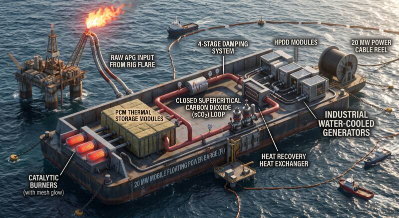
20 MW mobile floating power barge, fully engineered for deployment directly at extraction sites utilizing flared associated petroleum gas (APG).
Offshore Platform Power: The Hydro Puls Direct-Drive (HPDD) Case Study
A gas turbine trip offshore can halt artificial lift, compromise water injection, trigger flaring, and lead to massive production deferment. Mature offshore assets often inherit sub-optimal power architectures: large central turbines run inefficiently at partial loads, while prime movers are separated from heavy pumps and compressors by multiple electrical conversion stages (fuel to shaft, generator, switchgear, motor, and pump). Each interface introduces parasitic losses, maintenance footprints, and failure risks.
The modular Hydro Puls Direct-Drive (HPDD) architecture replaces this fragmented approach by delivering power, heat recovery, and fluid pressure directly from an autonomous energy core.
Core Technical Advantages
- Isolated Combustion Environment: Combustion is mechanically decoupled from traditional crankshafts, transferring energy directly to a working fluid. This allows the thermal process to run within its optimal efficiency window while buffering platform load variations hydraulically.
- Direct Hydraulic Coupling: High-pressure hydraulic power directly drives energy-intensive equipment—such as critical water injection pumps, compressors, and winches—bypassing intermediate motor-generator conversions.
- Accumulator Load Buffering: Hydraulic accumulators absorb transient spikes and enable black-start capability, dampening rapid load fluctuations and drastically reducing reliance on heavy battery energy storage systems (BESS).
- Dual-Bus Distribution: Independent modules supply a high-pressure hydraulic bus for mechanical work alongside an electrical package dedicated to controls, lighting, variable-speed equipment, and accommodation utilities.
- Integrated Thermal Management: High-grade process heat is recovered directly for separation, produced-water treatment, accommodation heating, or absorption cooling, eliminating discrete fired utility packages.
- N+1 Reliability: Multiple standardized modules eliminate the single-point-of-failure vulnerability of central turbines. Maintenance, overhauls, or module replacements can occur without shutting down the entire platform.
- Decoupled Fuel Flexibility: The separated combustion chamber allows future transitions to hydrogen, ammonia, or varying gas qualities without redesigning downstream pumps, distribution lines, or drives.
- Architectural Comparison
- Drivetrain Complexity: Conventional systems route energy through a multi-stage chain (fuel to generator, switchgear, motor, and pump). HPDD transfers pulse energy directly to a common hydraulic bus.
- Load Dynamics: Turbines must continuously throttle to chase spikes; HPDD dampens shocks mechanically using accumulators to keep thermal combustion steady.
- Operational Redundancy: A single central turbine failure threatens full platform blackout, whereas modular HPDD units operate in an N+1 arrangement with hot-swappable capacity.
- Water Injection Integration: High-power water injection shifts from heavy electric motors to efficient, directly coupled hydraulic drives.
- The investment value extends far beyond fuel efficiency: it cuts offshore diesel logistics, preserves production uptime, minimizes deck weight, and enables phased capital deployment across late-life or greenfield assets.
| Parameter | Conventional Turbine Architecture | Modular HPDD Solution |
|---|---|---|
| Drivetrain Path | Multi-stage: Fuel → Gen → Motor → Pump | Direct: Isolated combustion → Hydraulic bus |
| Transient Handling | Turbine throttled / BESS required | Direct hydraulic accumulator buffering |
| Redundancy | High risk (1–2 large central turbines) | Modular N+1 independent units |
| Water Injection | Large electric motor drive | Direct hydraulic drive coupling |
The current standard practice at remote drilling sites and fields relies on heavy barges or onshore facilities utilizing classical gas turbines and diesels. They are fuel-sensitive, require complex gas conditioning, and suffer massive efficiency losses. We are offering a complete departure from this obsolete hardware.
Our turbine-free alternative:
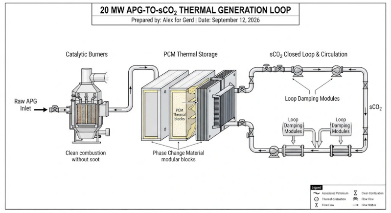
Fuel is utilized locally via catalytic burners, handling raw APG cleanly without soot formation or feedstock purchasing costs.
The generated heat is buffered in PCM (phase change material) thermal storage modules, smoothing out any thermal fluctuations.
A stable thermal flow is captured by the working fluid within a closed supercritical carbon dioxide (sCO_2) loop.
A 4-stage damping system integrated directly into the sCO_2 loop completely suppresses hydraulic and thermal pulsations.
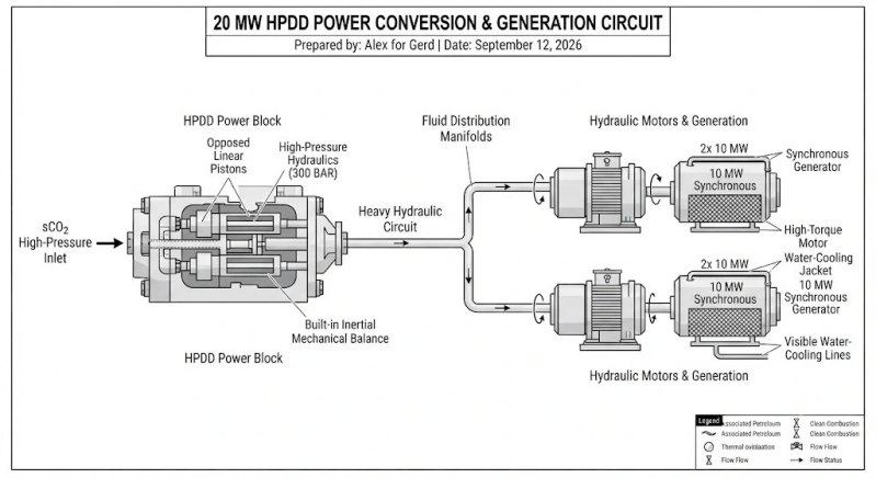
The clean power is transferred via HPDD modules to a heavy-duty hydraulic circuit, driving industrial water-cooled generators.
No cryogenic LNG tanks, pure thermodynamics with zero turbine losses, and a payback period within 1.5–2 years driven by zero-cost flared gas in real field conditions.
1. Thermal Balance & Efficiency Breakdown
Target Electrical Output: 20 MW (2x 10 MW water-cooled generators).
Catalytic Burners: Operating on raw, flared Associated Petroleum Gas (APG) with an LHV 38 MJ/m3. Thermal efficiency = 92%. Required thermal input: 60 MWth (approx. 5,700 m 3 h of flared gas).
PCM Thermal Storage: Phase Change Material modules buffer temperature swings with = 98\% heat transfer efficiency.
sCO_2 Closed Loop: Transcritical Brayton cycle conversion efficiency: approx 43%.
HPDD Power Block: Direct volumetric conversion of sCO_2 expansion into a 300 BAR hydraulic fluid column via opposed linear pistons. Efficiency: = 91%.
Hydraulic Generation: High-torque hydraulic motors driving water-cooled industrial generators. Efficiency: = 93\%.
Total System Efficiency approx 33.4% (exceptional for a zero-cost fuel flare-reduction application with zero cryogenic overhead).
2. sCO_2 Loop Damping & Mechanical Integration
The system integrates fluid-dynamic loop damping with the opposed linear piston configuration of your HPDD units. Together, they cleanly stabilize near-critical sCO_2 phase behavior, smooth out thermal-hydraulic ripples, and naturally cancel secondary mechanical vibrations to deliver a continuous, high-pressure hydraulic drive (300 BAR) to the generators.